所需工具:
1. Hex Key 2.5mm
2. Hex Key 3.mm
三。螺旋传动
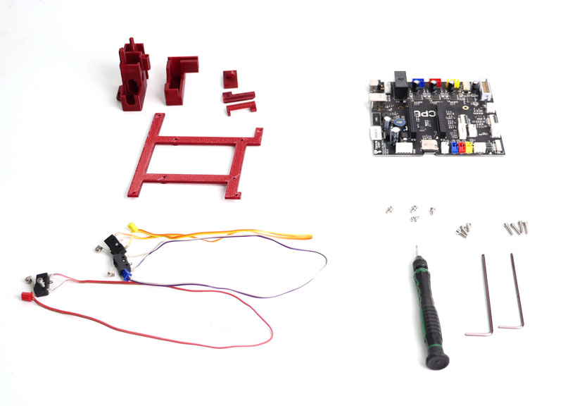
| Cetus MK2至MK3零件清单BC0881 | ||||
| 项目 | SKU | Name | 规格 | QTY |
| 1 | 25007 | T-nuts | M3×10mm | 2 |
| 2 | 25119 | Cable tide | 64mm,adjustable strap | 1 |
| 3 | BC0751 | MK3主板 | 1 | |
| 4 | 04151 | flat head self-drilling philip screw | ST2.5*8 | 6 |
| 5 | 04158 | 沉头螺钉 | M3×5 | 10 |
| 6 | 041107 | 沉头螺钉 | M2.5*12 | 8 |
| 7 | 04157 | 沉头螺钉 | 立方米*8 | 8 |
| 8 | 40060 | Hex screw | 立方米×12 | 2 |
| 9 | 25547 | 带电缆的X限位开关 | cable:400mm,2P蓝色连接器 | 1 |
| 10 | 25548 | Y limit switch with cable | 电缆:300mm,2P红色连接器 | 1 |
| 11 | 25549 | Z limit switch with cable | cable:250mm,2P yellow connector | 1 |
| 12 | 25550 | YZ limit swithc relay cable | 电缆:330mm | 1 |
| 13 | 25554 | mainboard ground wire | 5pin×80mm | 1 |
| 14 | BC0872 | Extension PCB kit | 1 | |
其他所需组件:
升级后,如果用户安装加热搭建平台,则无法使用原电源为机器供电。用户必须使用220W电源(库存单位:XS028).

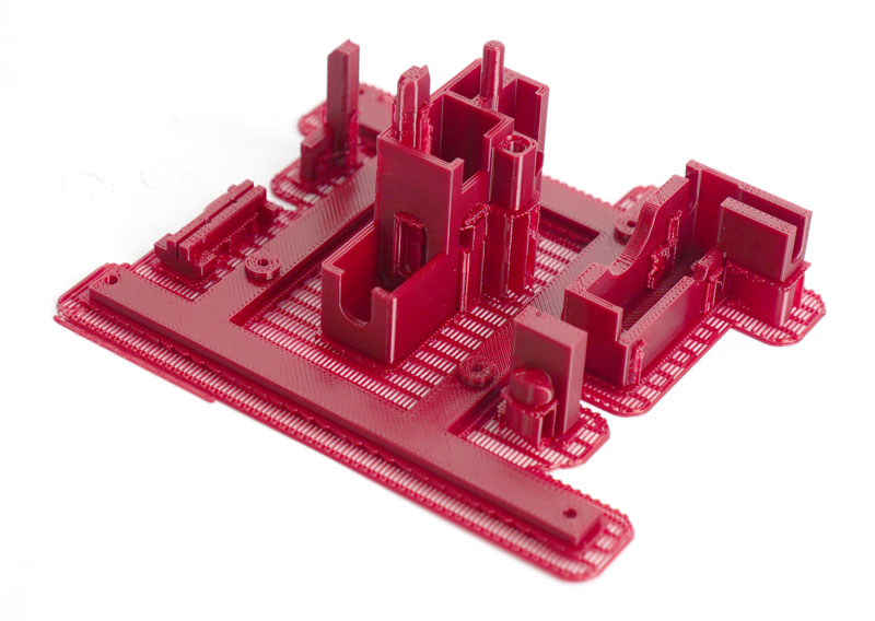
Step 1. Print Plastic Parts Required for Upgrade
Before dissasembling everything, printer out the parts required.
Download the following file for the printable parts:
Step 2. Dissamble the Machine.
2.1. 通过拆下3个SCRW来拆下平台。

2.2 Remove the 4 screws to the bottom of machine.
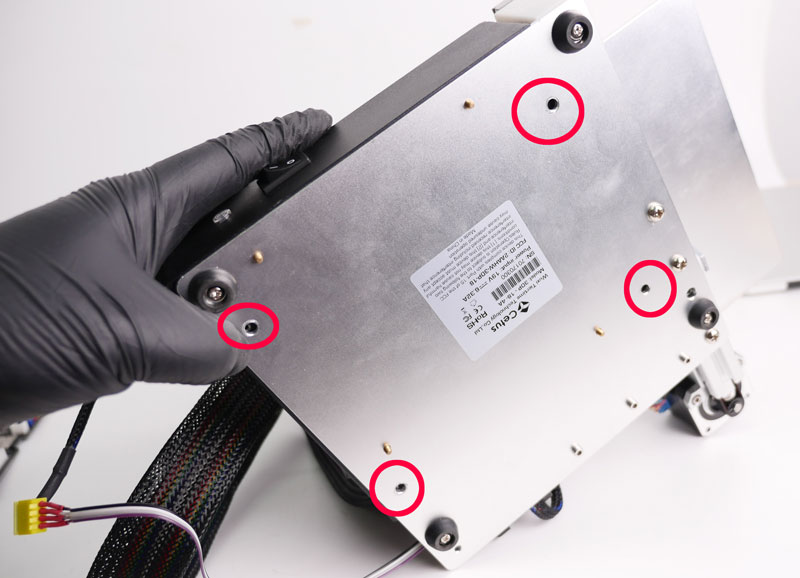
2.3. Remove the power cable and the initialization button cable.
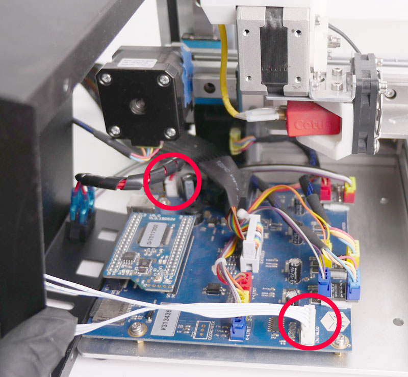
2.4. Remove CPU. Before remove the CPU, discharging yourself is recommended, also be careful not to bend the pin of the CPU board.
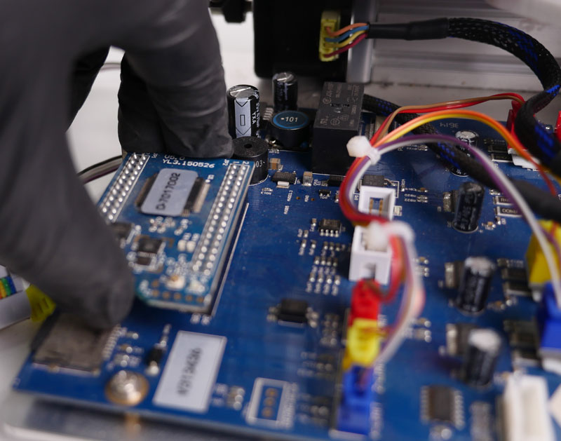
2.5. Remove the SD card on mainboard.

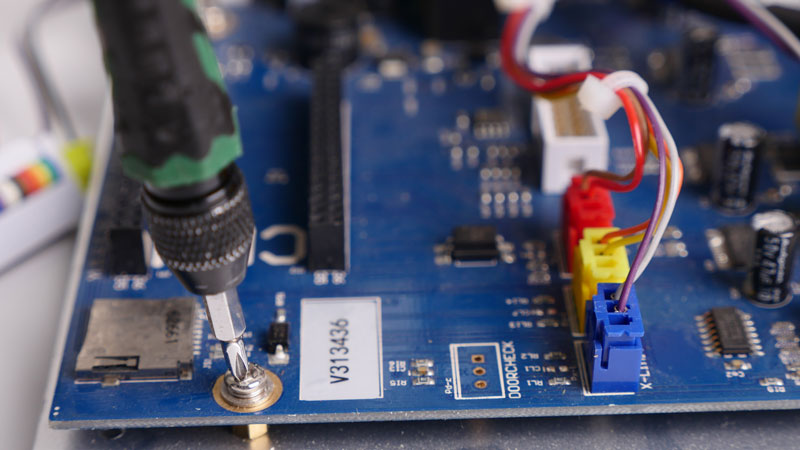
2.6. 卸下主板上的4颗螺丝,拔下挤出机电缆、电机电缆,卸下主板。
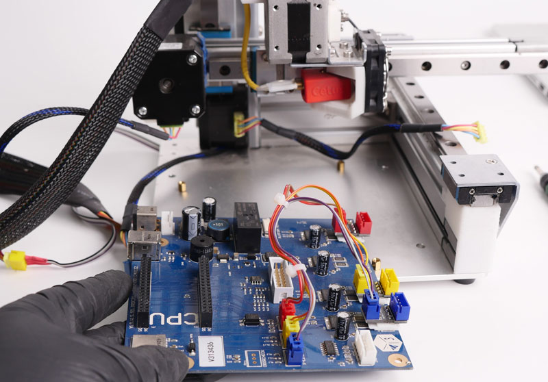
Step 3. Install MK3 Mainboard.
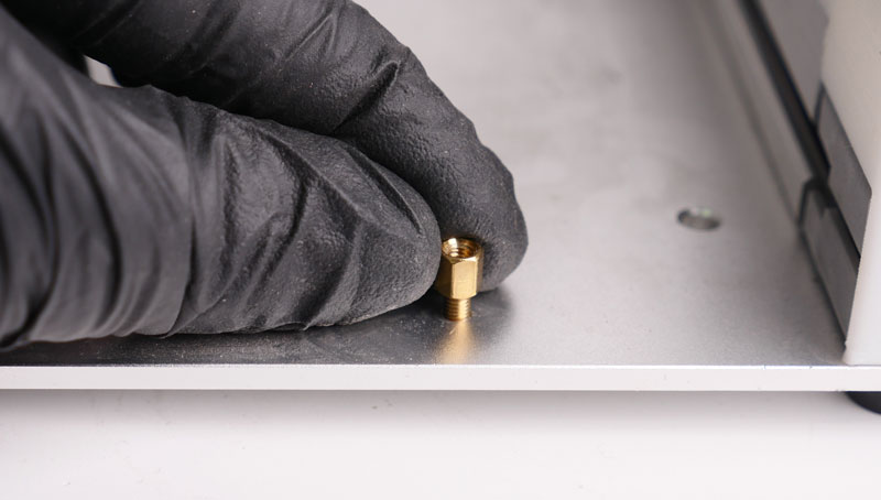
3.1 Remove brass nuts by hand
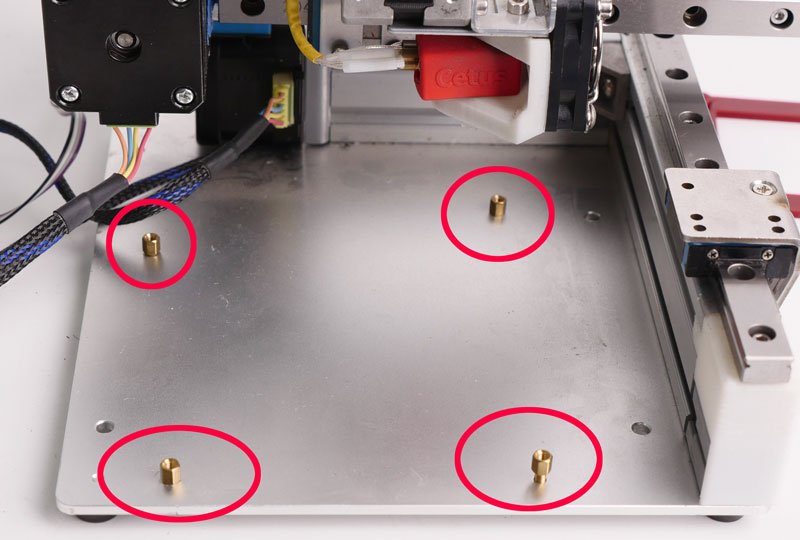
3.2 Install the Mainboard Adaptor and MK3 Mainboard.

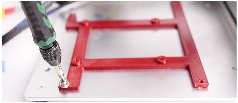
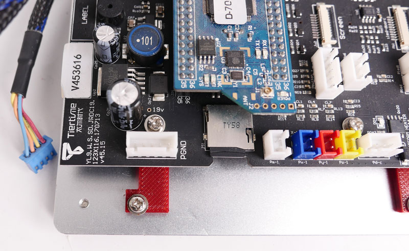
3.3. Install MK3 Mainboard, CPU and SD card.


3.4. Connect Ground Cable (reduce risk of static charge damage to electronics)

Step 4. Install Y-axis Limit Switch and Trigger.
4.1. 拆下螺钉
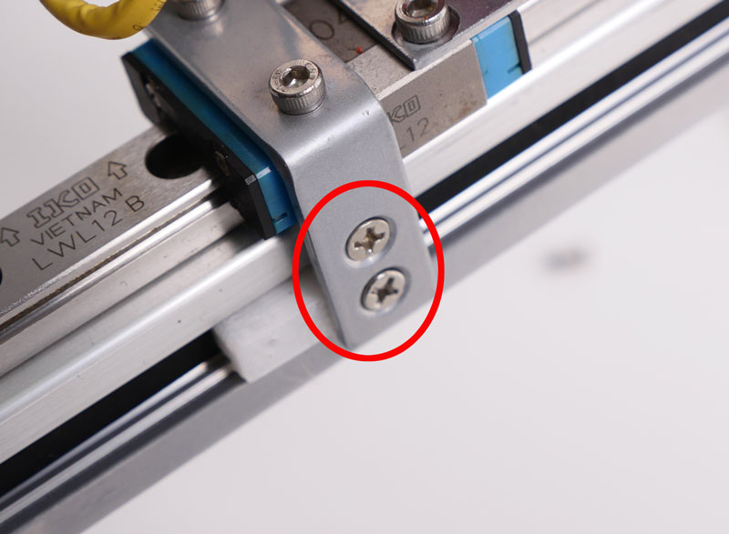
露出原来的Y触发器

4.2. 拧松皮带背面的螺钉,取下打印部分。Do not remove the screw from the belt, keep it on the belt!
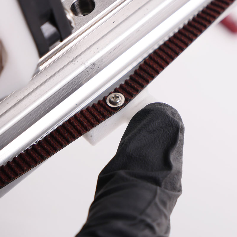
4.3. Install the New Y Limit Switch Trigger
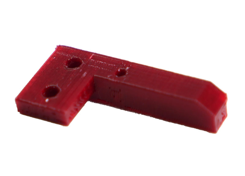
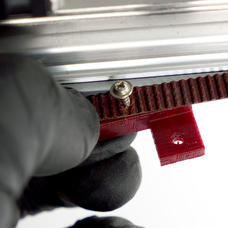
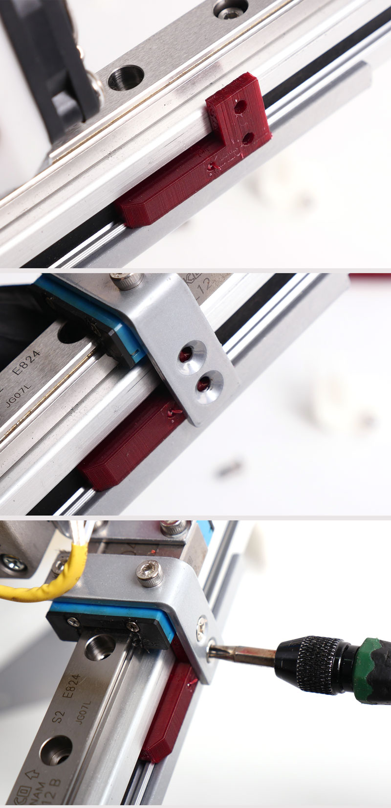
第五步。安装Y轴限位开关
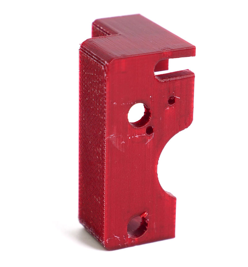
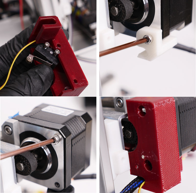
5.1. Install the limit switch on the holder.
5.2. Remove the original printed part and the screw on the motor.
5.3. Install limit switch holder onto the Y-axis motor.
Step 6. Install the X-axis Limit Switch
X轴限位开关支架
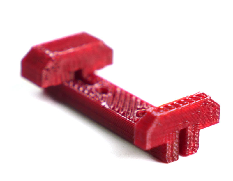
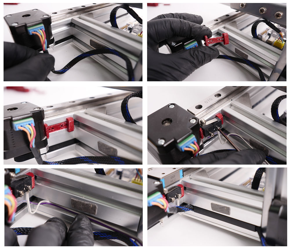
6.1 Open the slot cover on the back of the printer.
6.2将支架压入槽中,安装限位开关。
6.3将电机电缆和限位开关电缆放入槽中,然后压装槽盖。
Step 7. Install Extension PCB
May also refer to follwoing articles:
Detailed Guidance on Extension Board Installation and Limited Switch Issues
7.1 Uninstall the Z-cap
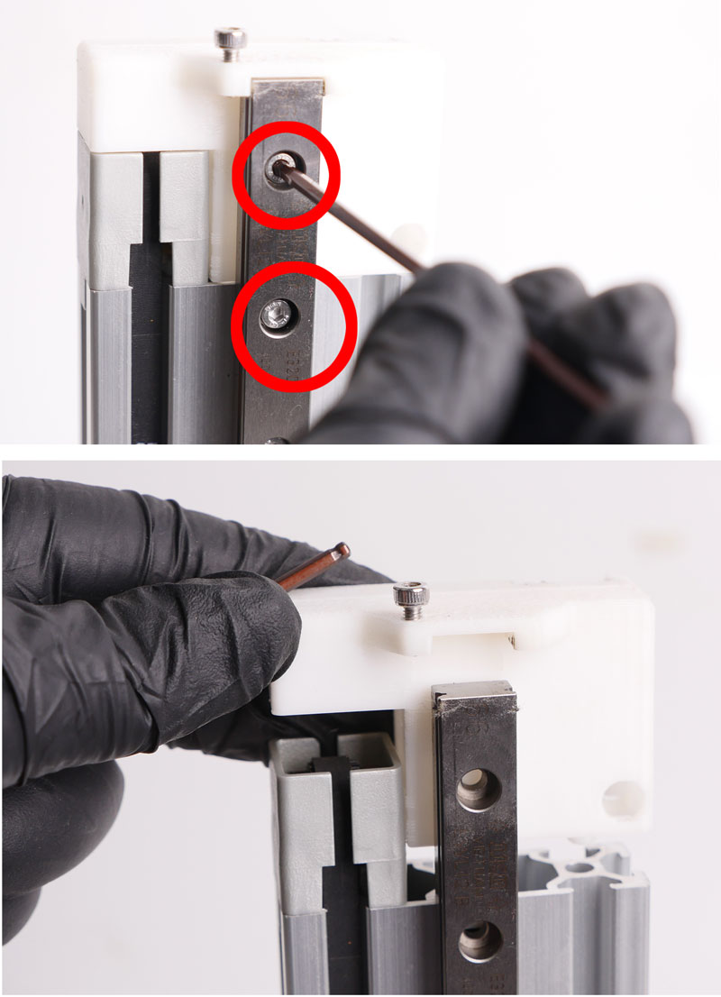
7.2 Slide the extension board into extrusion slot.

第8步。安装MK3 Z轴盖和限位开关。
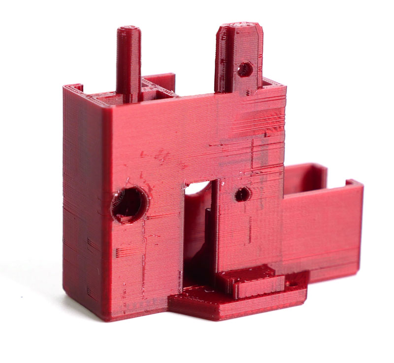
8.2安装Z轴限位开关。
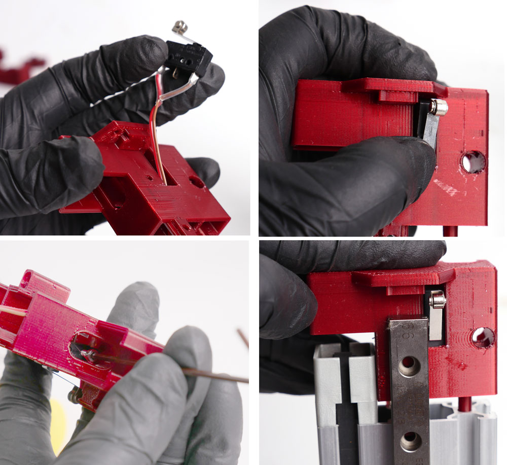
第9步。连接电缆

9.1 Connec Z-limit switch and Y-limit switch to the extension board. Follow the color.
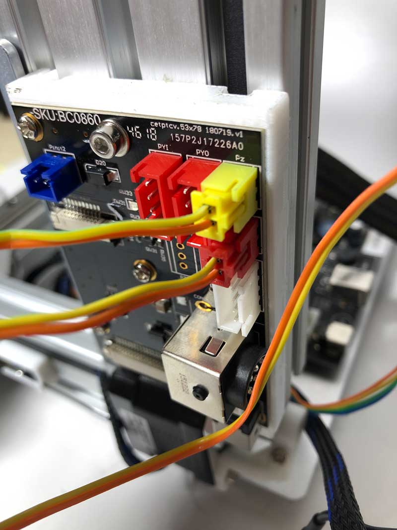
9.2使用附带的继电器电缆将限位开关从扩展PCB连接到主板。
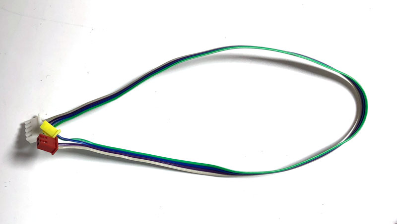

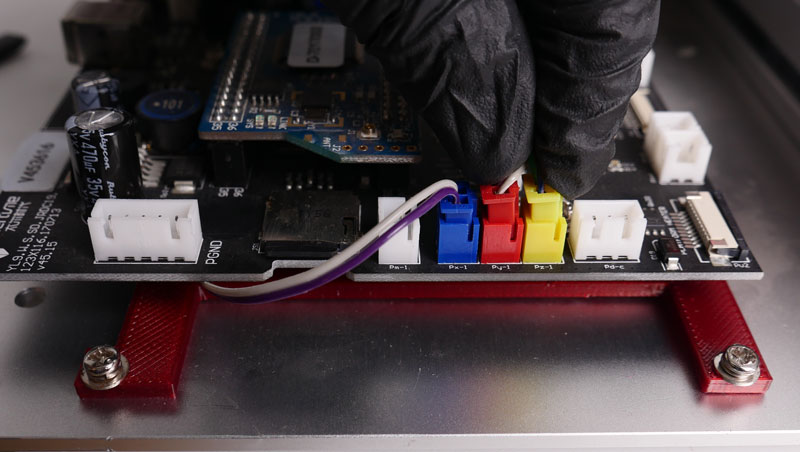
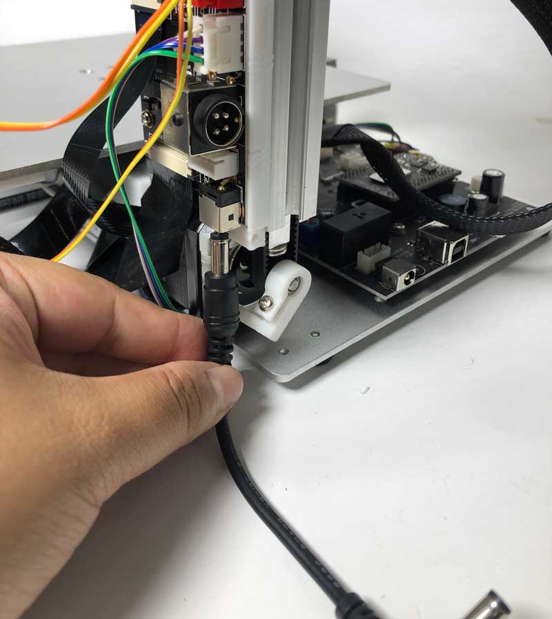
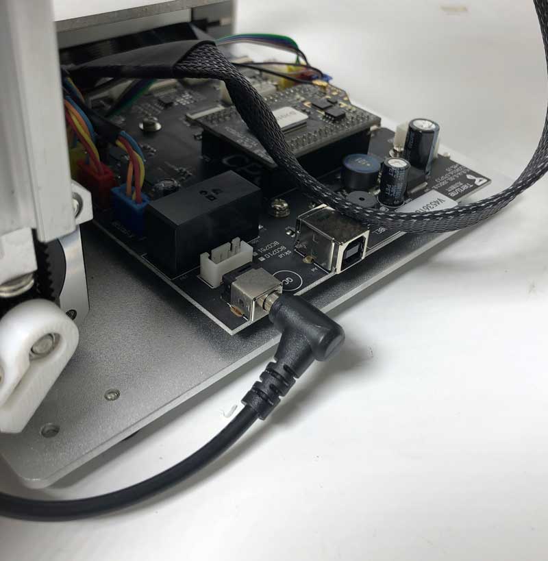
9.3将电源线从扩展PCB连接到主板
9.4松开带状电缆的连接器(标记为“平台加热器”)。将电缆插入连接器,金属销朝向主板。
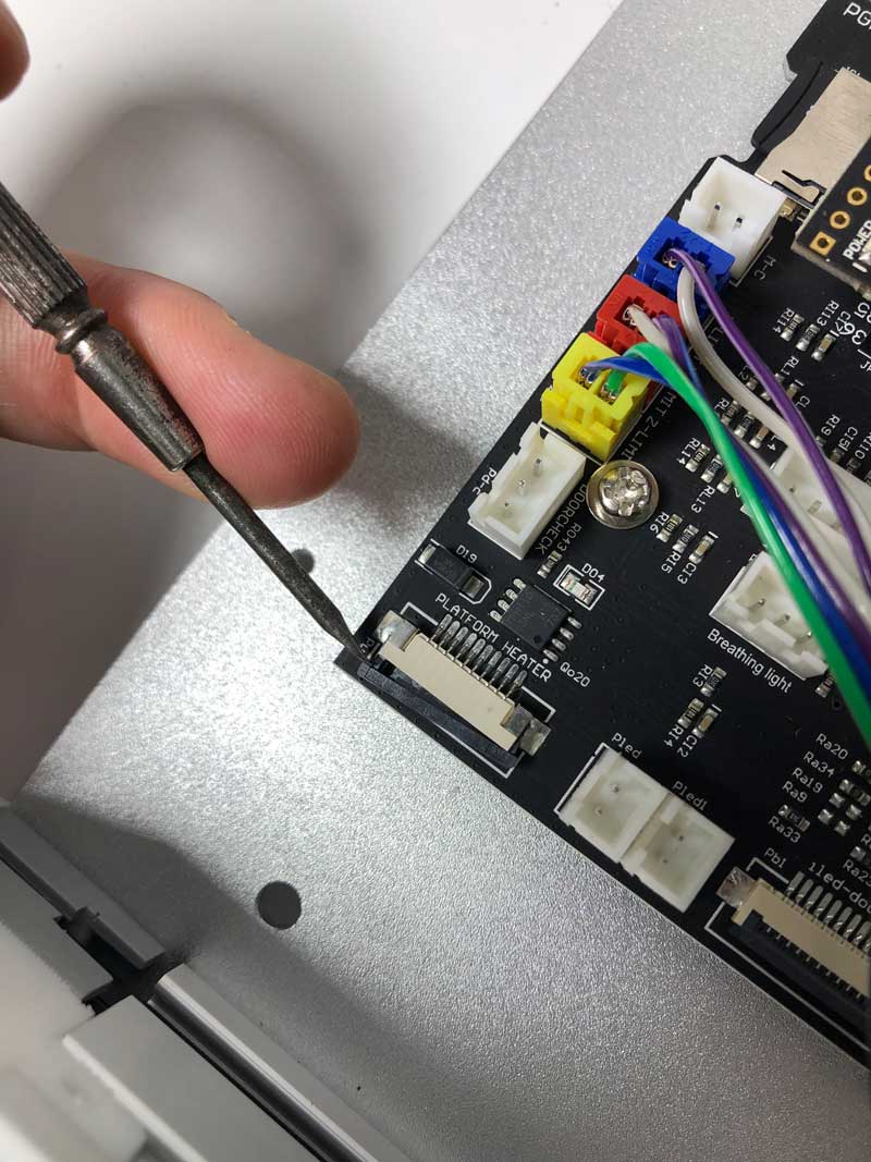
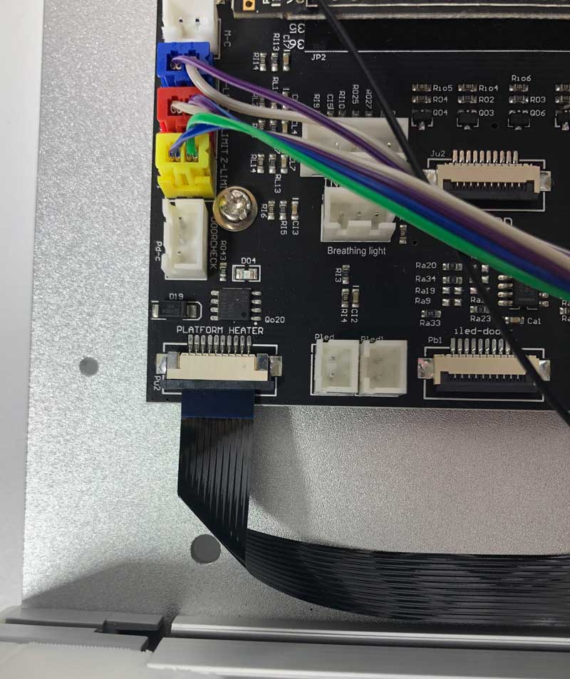
9.5电缆折叠成形状像the red line indicated below.
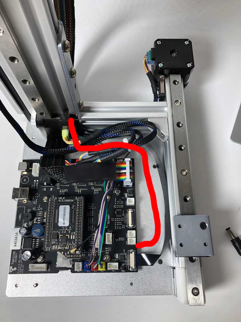
9.6将带状电缆穿过电机和Z轴支架之间的空间。

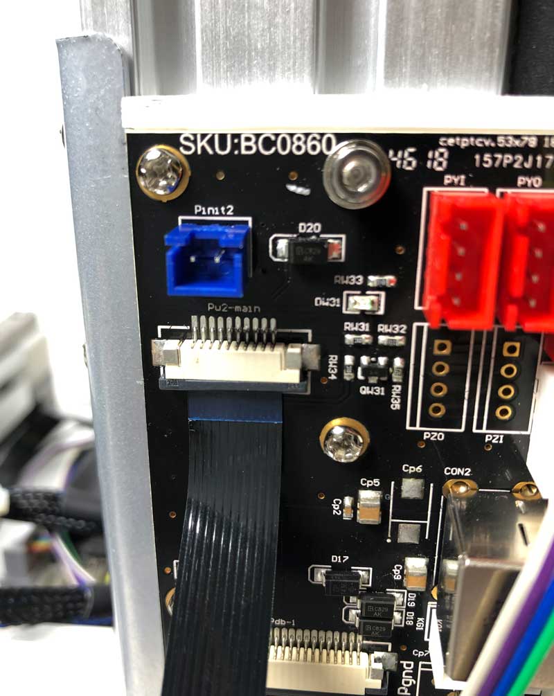
9.7 Fold the cable upward and insert into the connector, metal pins facing toward extension board.
This ribbon cable is important for temprature control of heated bed upgrade and autoleveling.
第10步。安装Wifi天线
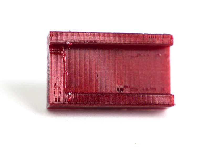
10.1 Insert the antenna holder into the slot of the back of machine, turn it 90 degrees to lock it in position.
10.2 Insert the antenna into the holder and connect the other end to CPU.
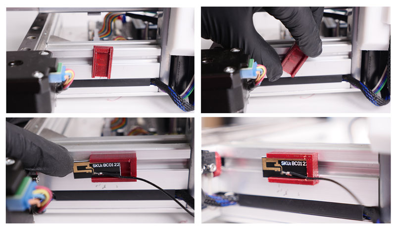
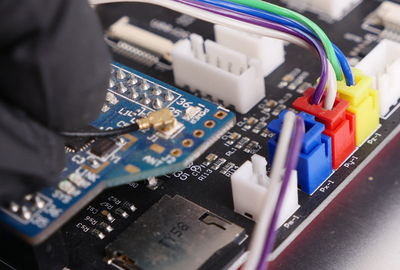
10.3 Make sure the cables are well sorted, no tangling. Install the PCB cover.

10.4. Lock the PCB cover.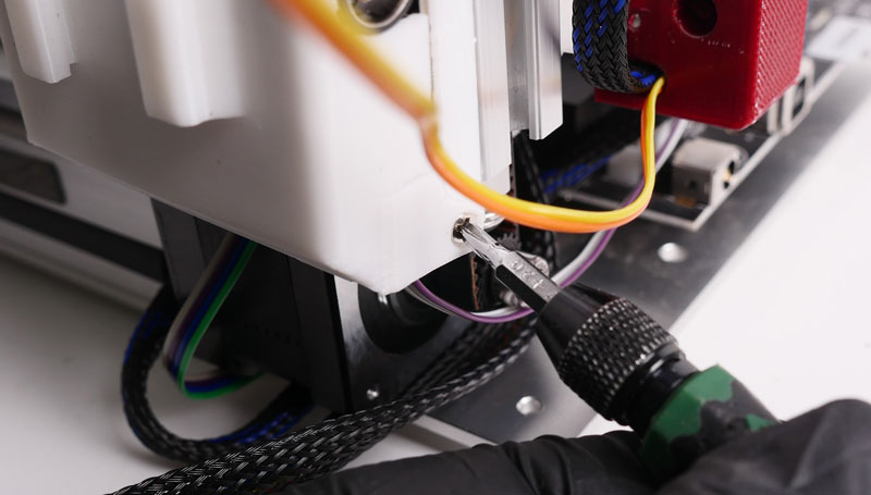
10.5. Lock the extruder cable along the Z-axis
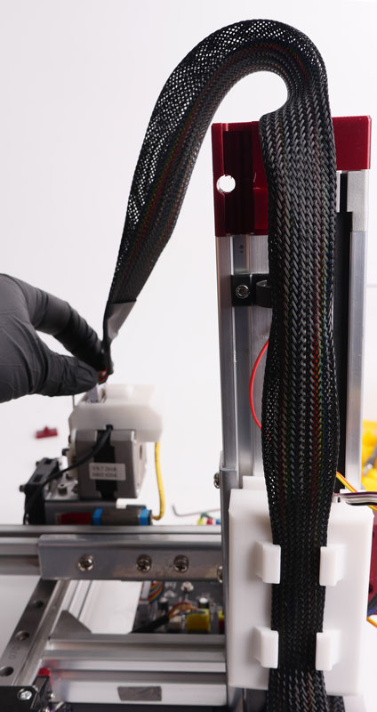
第十一步。ROM更新:
CPU rom必须在机器可用前更新,请参阅以下信息更新您的rom。
| MK3标准版ROM: | 鲸蜡S7NTC_R_180524 MK3-STD.ROM |
| MK3 Extended Version ROM: |


评论
9 comments
Can the mk1 use this kit too?
我在安装升级:第5项&套件中的7与上述规格不同;接地线不同(没有5路插头连接到PCB),并且如果如上图所示将黄铜支架安装在主板适配器上,USB/电源插座将不会与机箱中的孔对齐-看起来板需要直接安装或需要将压铆螺母柱移到基板上的新钻孔和螺纹孔中,然后丢弃压铆螺母柱。我将提交一个支持请求-不确定这些评论是否被监视。
Will Tiertime issue signed drivers for Windows?
I have completed the hardware upgrade, but now can't upgrade the ROM, as Windows does not have the correct drivers. I tried downloading the drivers from the website, but these are still not signed and so will not install.
关闭Widows安全功能以强制安装不是理想的解决方案。
嗨,工具包有不同的错误:
1. the 3d printed parts are not ok
https://support.tiertime.com/hc/article\u attachments/360042023454/upgrade\u parts.up3
对于z轴,我不得不使用原来的盖子为末端挡块打一个孔,因为打印机的线性导轨似乎更短(黑色部分是上面链接的新部分(不适合)。
安装主板时,它离基板边缘太近,所以我无法再装上盖子。因此,我不得不钻4个孔在基板上移动主板约5毫米的中间。
安装完所有的硬件后,我给CPU闪存了
https://support.tiertime.com/hc/en-us/article\u attachments/360042033694/Cetus\u S11NTC\u R\u 180524\u MK3-EXT.ROM
seems to work...but.... the hardware Init switch did not work anymore !!!!!!
Init via software is working and the endstops are working too.
But thats not all !!!
当我想打印的第一次(阿尔夫找平当然)喷嘴第一次清洁(一条直线),这是确定的。但是,当开始第一个筏层线喷嘴似乎挖到打印床。
y轴和z轴同时移动。
https://youtu.be/xE2j11haqVQ
So I dont know whats wrong and I need support
我对底盖也有同样的问题。这是唯一的解决办法吗?不过,印刷还是不错的。
It works for me:主板转接板(混音)
And: I mounted the board directly on the adapter.
It seems that they forgot to remove the v-groove edge rails from the PCB. After removing them carefully with pliers the PCB fits perfectly in the case with the original adaptor.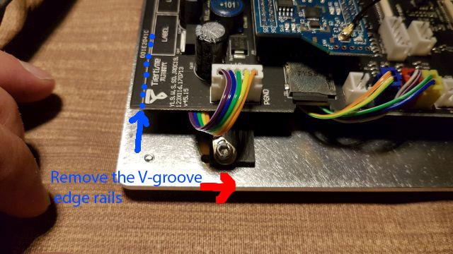
i cant get anything to work after Rom flashing attempt. It only took 1 second so I don't think it flashed the new firmware. Anybody?
I have the Problem, that after flashing the rom, connecting the momentary switches and doing evrything above (plus the adjustments in the coments), the printer just ignores them and jamms right in the z-Axis stopper. In the Up studio software there is an system error, after reinstalling the rom using the utility software that error was gone. Problem is still there. please Help
Pleasesign into leave a comment.